We going to tear to pieces 1TB Seagate ST31000333AS drive. Let's take a look on our "Guinea pig".
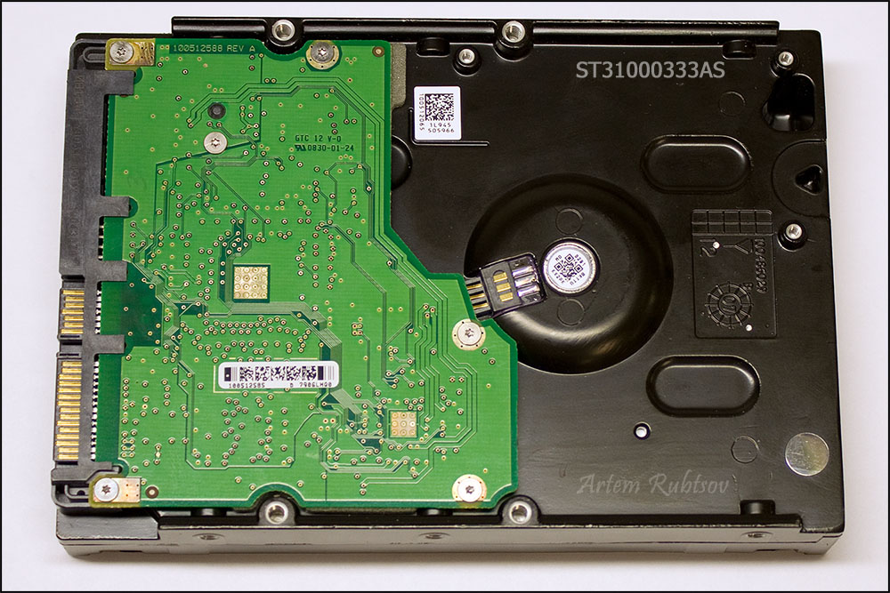
The fancy piece of green woven glass and copper with SATA and power connectors called Printed Circuit Board or PCB. PCB holds in place and wires electronic components of HDD. The black painted aluminum case with all stuff inside called Head and Disk Assembly or HDA. The case itself called a Base.
Now let's remove PCB and see electronic components on the other side.
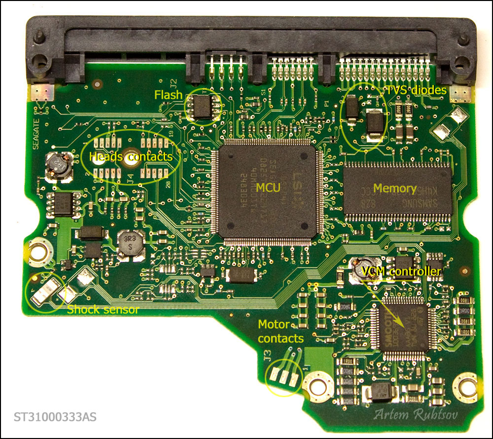
The heart of PCB is the biggest chip in the middle called Micro Controller Unit or MCU. On modern HDDs MCU usually consists of Central Processor Unit or CPU which makes all calculations and Read/Write channel - special unit which converts analog signals from heads into digital information during read process and encodes digital information into analog signals when drive needs to write. MCU also has IO ports to control everything on PCB and transmit data through SATA interface.
The Memory is DDR SDRAM memory type chip. Capacity of the memory chip defines capacity of the cache of HDD. This PCB has Samsung 32MB DDR memory chip which theoretically means the HDD has 32MB cache (and you can find such information on a data sheet for this HDD) but it's not quite true. Because memory logically divided on buffer or cache memory and firmware memory. CPU eats up some memory to store firmware modules and as far as we know only Hitachi/IBM drives show real cache size in data sheets for the other drives you can just guess how large is the real cache size is.
Next chip is Voice Coil Motor controller or VCM controller. This fellow consumes the most of electircal power on PCB. It controls spindle motor rotation and heads movements. The core of VCM controller can withstand working temperature of 100C/212F.
Flash chip stores part of the drive's firmware. When you apply power to a drive, MCU chip reads content of the flash chip into memory and starts the code. Without such code drive wouldn't even spin up. Sometimes there is no flash chip on PCB that means content of the flash is located inside MCU.
Shock sensor can detect excessive shock applied to a drive and send signal to VCM controller. VCM controller immediately parks heads and sometimes spins the drive down. It theoretically should protect the drive from further damage but practically it doesn't, so don't drop your drive - it wouldn't survive. On some drives shock sensors can detect even lightest vibrations and signals from such sensors would help VCM controller to tune up heads movements. Such drives should have at least two shock sensors.
Another protection device called Transient Voltage Suppression diode or TVS diode. It protects PCB from power surges of external power supply. When TVS diode detects power surge it fries itself and creates short circuit between power connector and ground. There are two TVS diodes on this PCB - one for 5V and one for 12V protection.
Let's take a quick look on HDA
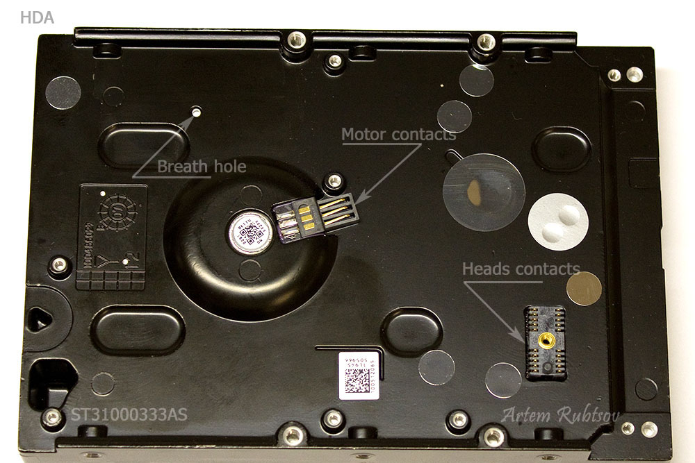
You can see motor and heads contacts that were hiding under the PCB. There is also small, almost unnoticeable hole on HDA. This hole is called a Breath hole. You maybe heard an old rumor that says that HDD has vacuum inside, well that is not true. HDD uses the Breath hole to equalize pressure inside and outside HDA. From the inside the Breath hole closed by a Breath filter to make air clean and dry.
Now it is time to take a look under the hood. We are going to remove the drive's lid.
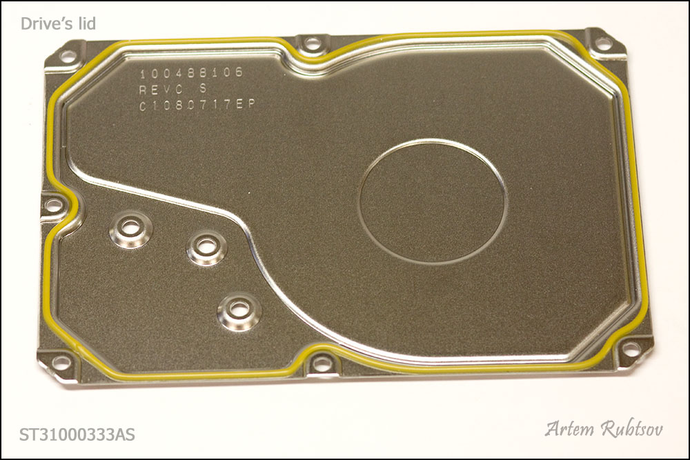
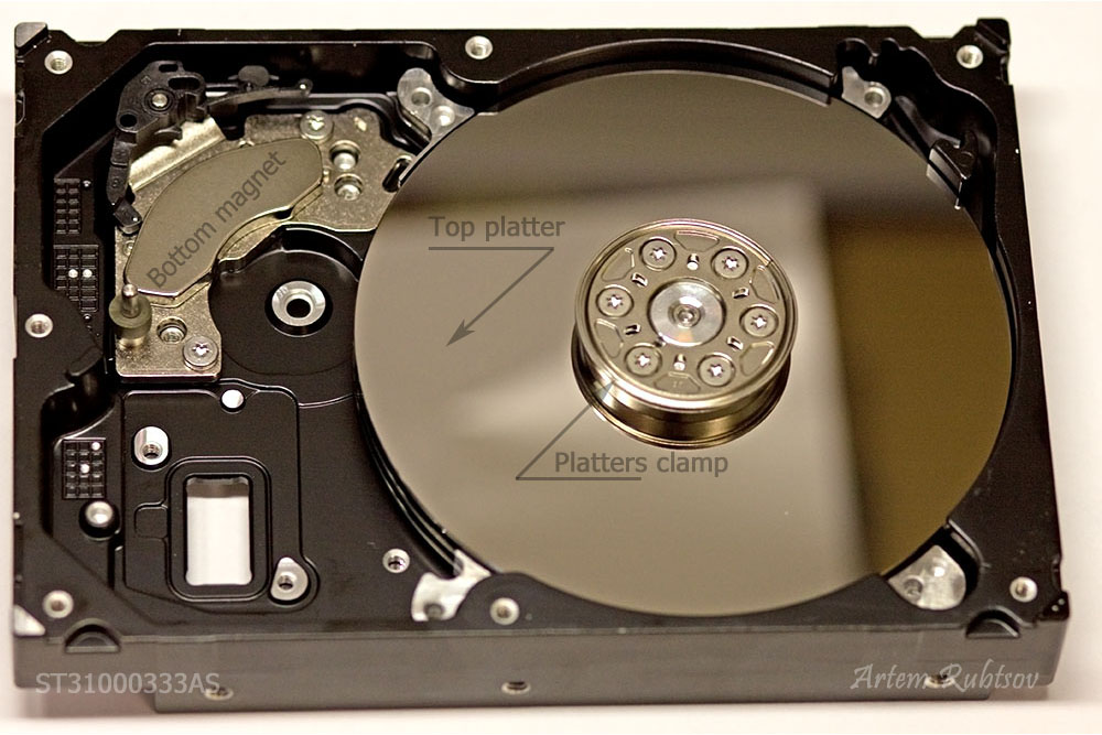
The lid itself is nothing interesting. Just a piece of steel with rubber cord for dust protection. Finally we are going to see HDA from inside.
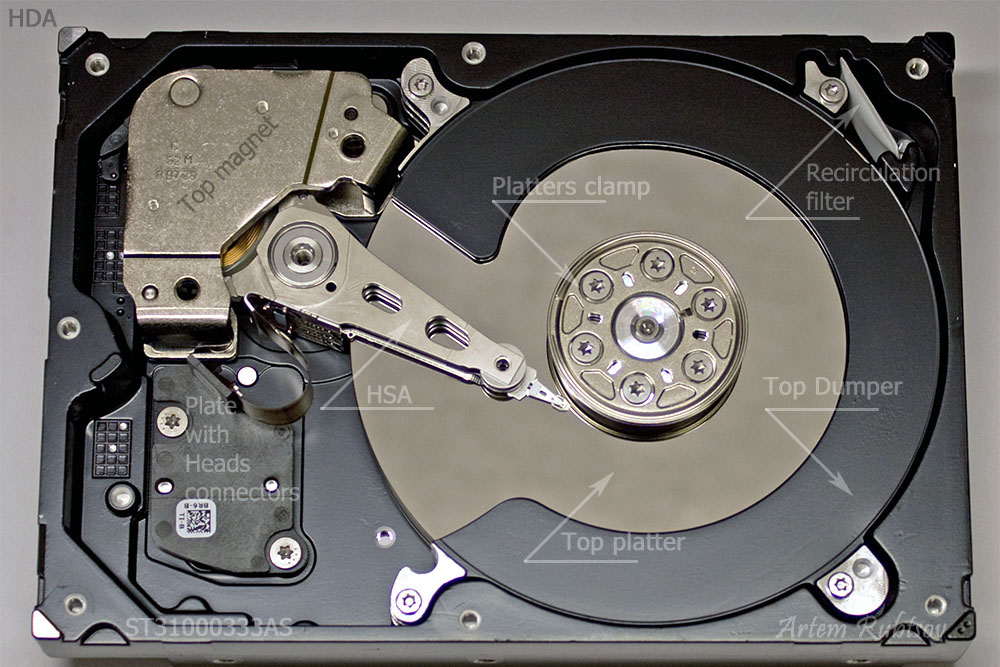
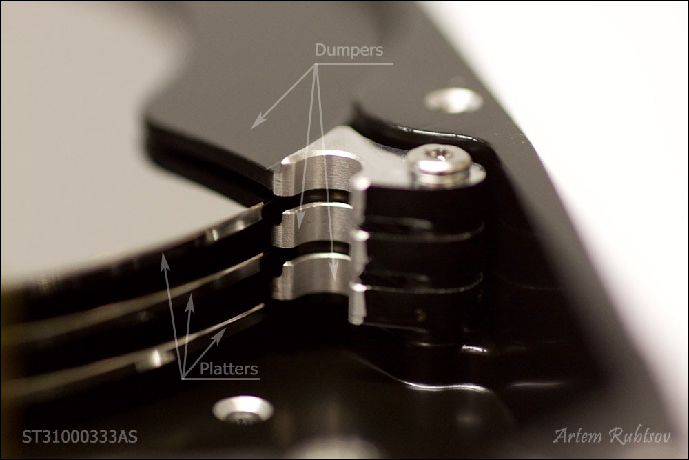
Precious information is stored on platters, you can see top platter on the picture. Platters made of polished aluminum or glass and covered with several layers of different compounds including ferromagnetic layer which actually stores all the data. As you can see part of the platter covered with the Damper. Dampers sometimes called as Separators located between platters, they reduce air fluctuations and acoustic noise. Usually dampers made of aluminum or plastic. Aluminum dampers are better for cooling air inside HDA.
Next picture shows platters and dampers from the side
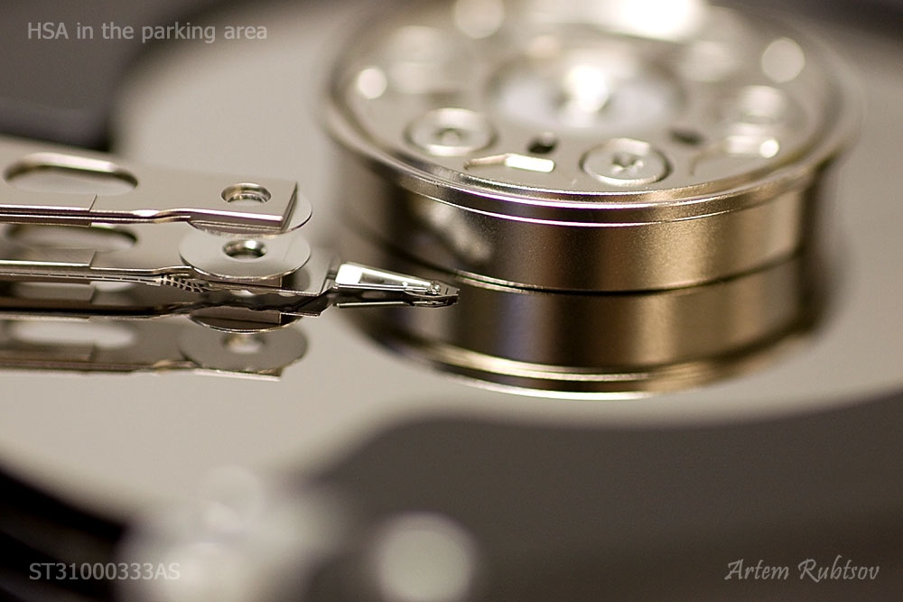
Heads are mounted on a Head Stack Assembly or HSA. This drive has parking area closer to the spindle and if power is not applied to a drive, HSA normally parked like on the picture.
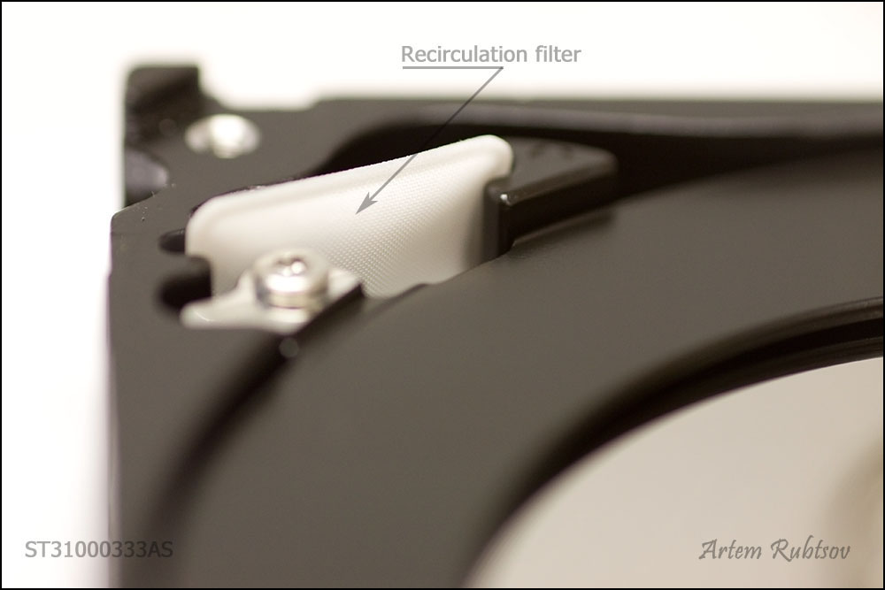
HDD is a precise mechanism and in order to work it requires very clean air inside. During work HDD may create some very small particles of metal and oil inside. To clean air immediately drive uses a Recirculation filter. This hi-tech filter permanently collects and absorbs even the finest particles. The filter located on the way of air motion created by platters rotation.
Now we are going to remove top magnet to see what is under.
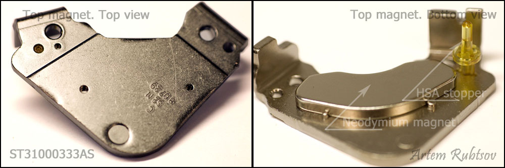
HDDs use very strong Neodymium magnets. Such a magnet is so strong it could lift up to 1300 times of its own weight, so don't put your fingers between the magnet and steel or another magnet - it can develop great impact. As you can see on this picture there is an HSA stopper on the magnet. HSA stoppers limit HSA movements, so heads wouldn't bang on the platters clamp and on the other side they wouldn't just fly off the platters. HSA stoppers may have different construction but there is always two of them and they are always present on modern HDDs. On this drive the second HSA stopper is located on HDA under the top magnet.
And here is what you may see under the top magnet.
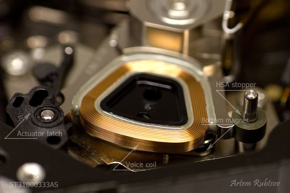
There is the other HSA stopper. And you also can see the second magnet. A Voice coil is a part of HSA, the Voice coil and the magnets form a Voice Coil Motor or VCM. VCM and HSA form the Actuator - a device which moves the heads. Tricky black plastic thingy called an Actuator latch is a protection device - it will release HSA when drive is un-parking (loading) heads normally and it should block HSA movements in the moment of impact if drive was dropped. Basically it protects (should, at least) heads from unwanted movements when HSA is in the parking area.
On the next step we are going to take out HSA
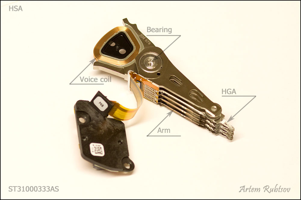
HSA has a precise bearing to make movements nice and smooth. The biggest part of HSA milled from a piece of aluminum called an Arm. Heads Gimbal Assembly or HGA is attached to the Arm. HGAs and Arms usually produced on different factories. Flexible orange widget called Flexible Printed Circuit or FPC joins HSA and plate with heads contacts.
Let's take a closer look on each part of HSA.
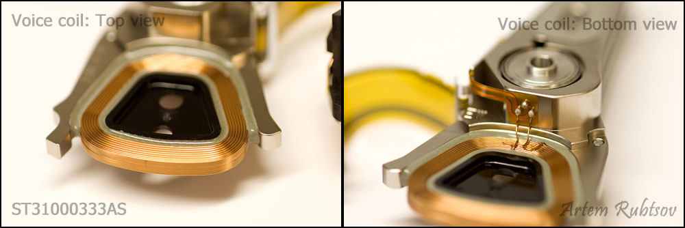
Voice coil connected to FPC
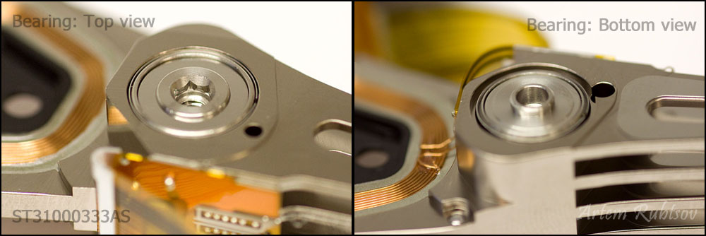
Here is the bearing
On the next picture you can see HSA contacts
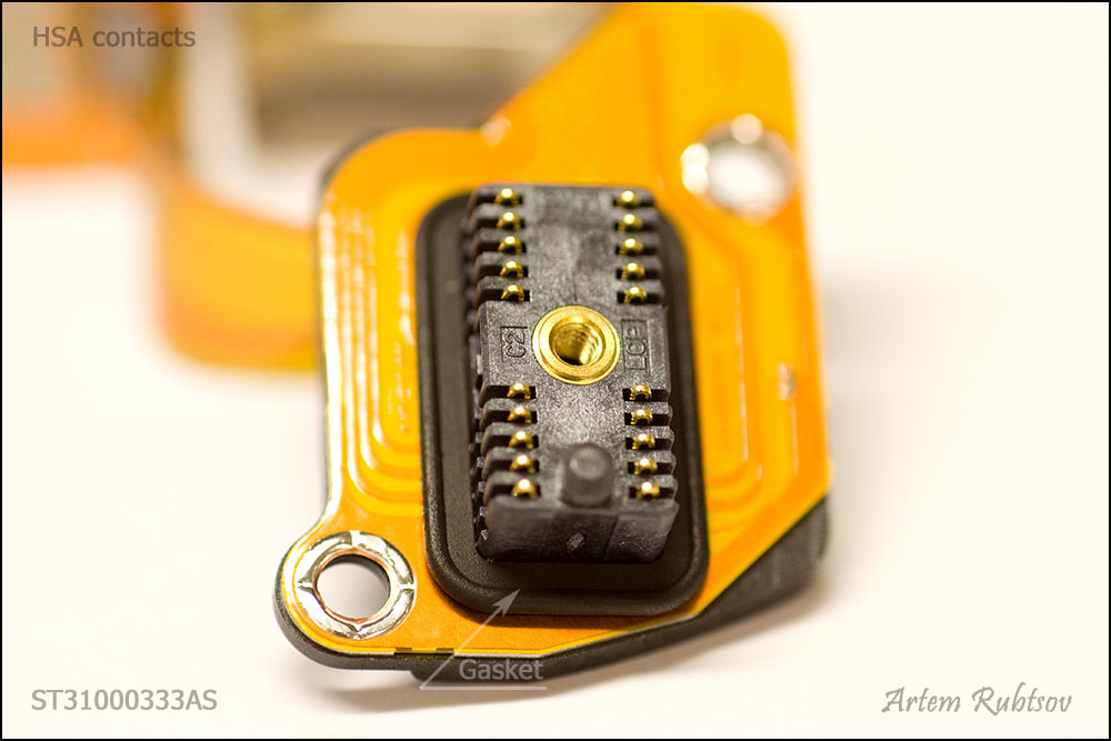
The gasket makes connection airtight. The only way for air to go inside HDA is through the breathing hole. On this drive contacts are covered with a thin layer of gold, for better conductivity.
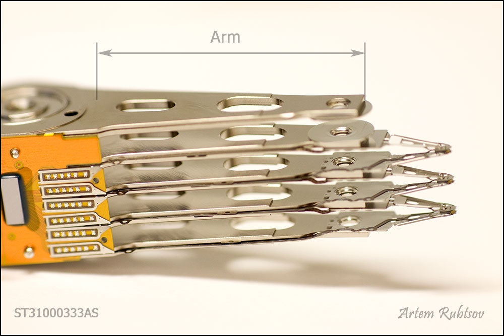
This is the classic definition of the arm. Sometimes the arm is implied to be the whole metal piece of HSA.
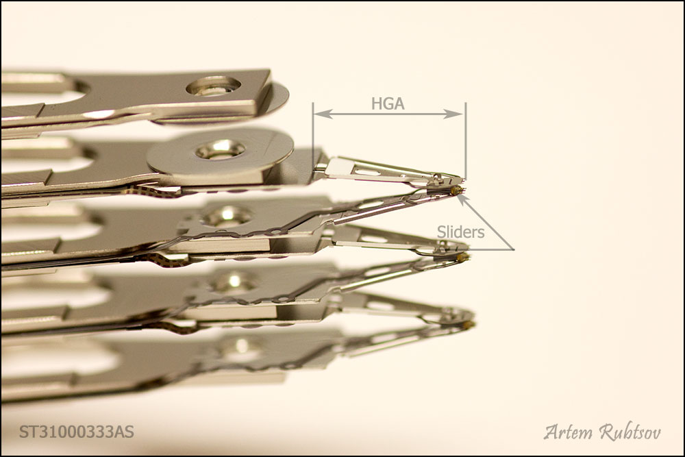
The black small things at the end of HGAs are called Sliders. In many sources you can find that sliders are claimed as actual heads but a slider itself is not a read/write head it's a wing that helps read and write elements fly above the platter's surface. Heads' flying height on modern HDDs is about 5-10 nanometers. For example: an average human's hair is about 25000 nanometers in diameter. If any particle goes under the slider it could immediately overheat (because of friction) the heads and kill them that's why clean air inside HDA is so important. The actual read and write elements located at the end of the slider and they are so small that can only be seen under a good microscope.
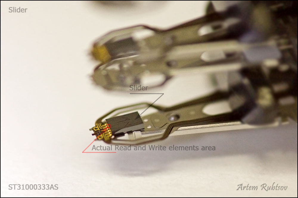
As you can see slider's surface is not flat, it has aerodynamic grooves. These grooves help the slider fly on a certain height. Air under the slider forms Air Bearing Surface or ABS. ABS makes slider fly almost parallel to the platter's surface.
Here is another picture of the slider
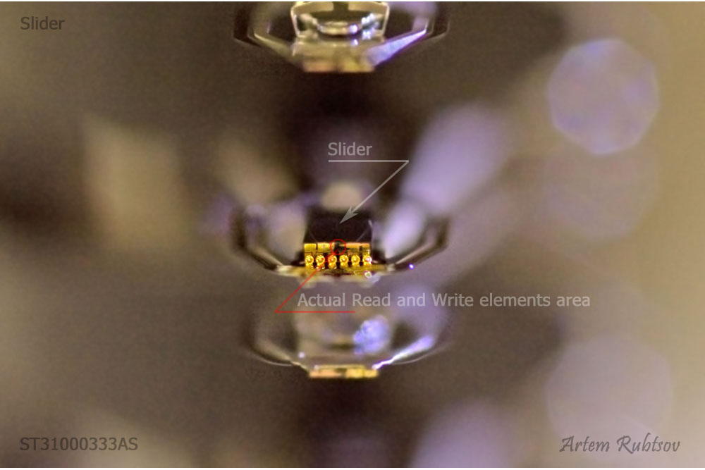
You can clearly see heads' contacts.
There is very important part of HSA which we haven't discussed yet. It's called a preamplifier or a preamp. The preamp is a chip, that controls heads and amplifies signals from/to them.
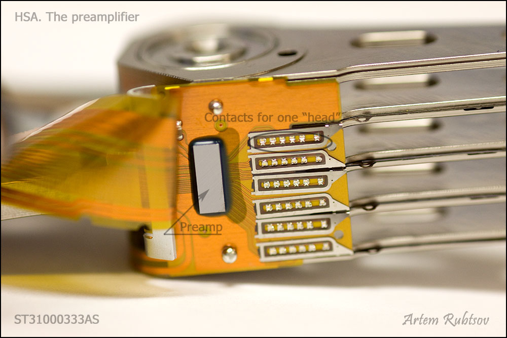
The reason why the preamp located inside HDA is simple - signals from heads are very weak and on modern HDDs are more than 1GHz in frequency, if to take the preamp out of HDA such weak signals wouldn't survive, they will disappear on the way to PCB.
The preamp has more traces going to the heads (right side) than to the HDA (left side), it's because HDD can work only with one "head" (pair of read an write elements) at a time. HDD sends control signals to the preamp and the preamp selects the head which HDD needs at the current moment. This HDD has six contacts per "head", why so many? One contact is for ground, another two is a diffirential pair for a read element. Another two is a diffirential pair for a write element. And finally the last contact is for a heater. The heater can help adjust heads flying height. The heater can heat the gimbal - special joint which connects slider to HGA, the gimbal is made from two stripes of different alloys with different thermal expansion. Once gimbal gets heated it bents itself toward platter's surface and this action reduces the head's flying height. After cooling down the gimbal straights itself. On newer HDDs there could be two more signals for microactuators - special piezoelectric devices that can move or rotate slider, it helps tune up heads position for a better track "following".
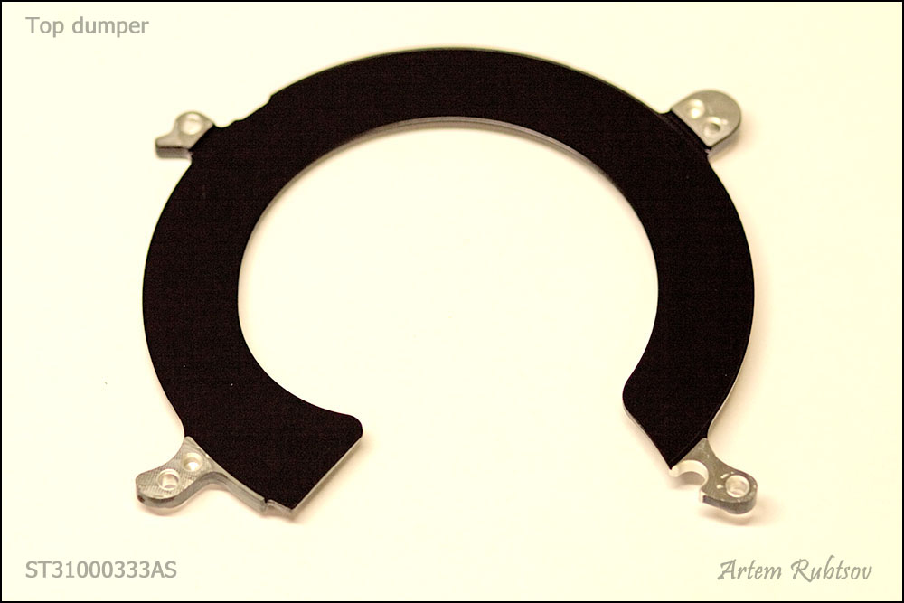
Enough about heads, let's continue disassembling. We are going to remove top damper.
That's how it looks
And next picture shows HDA without the top damper and HSA
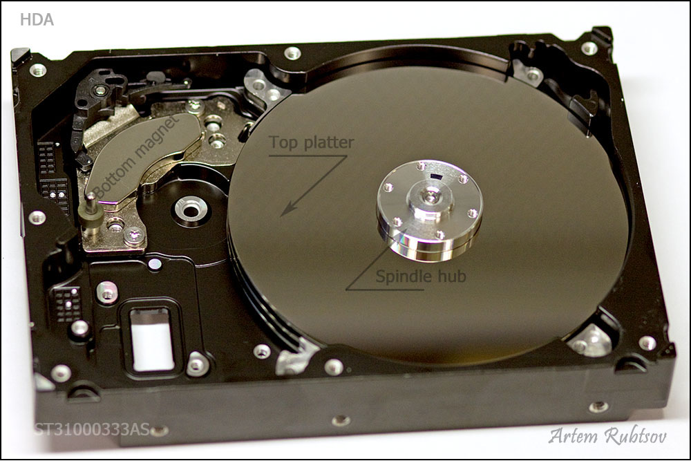
Now the top platter is not covered, and you also can see the bottom magnet
Let's move further and remove a platters clamp
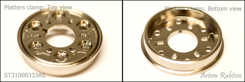
The platters clamp is holding platters in place, and squeezing them into the platters packet.
Platters are sitting on a spindle hub, the platters clamp creates enough friction to hold the platters on the hub when spindle rotates.
Now when nothing is holding the platters we are going to remove the top platter and next picture will show what we may see under.
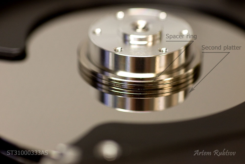
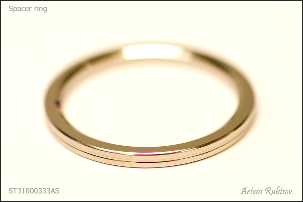
Now you see how the platters packet has a room for heads - platters are laying on spacer rings. You can see the second platter and the second damper.
The spacer ring is a precise detail made of non-magnetic alloy or polymer. Let's take it out.
Finally we are going to shake out the rest of the stuff from HDA and see the base
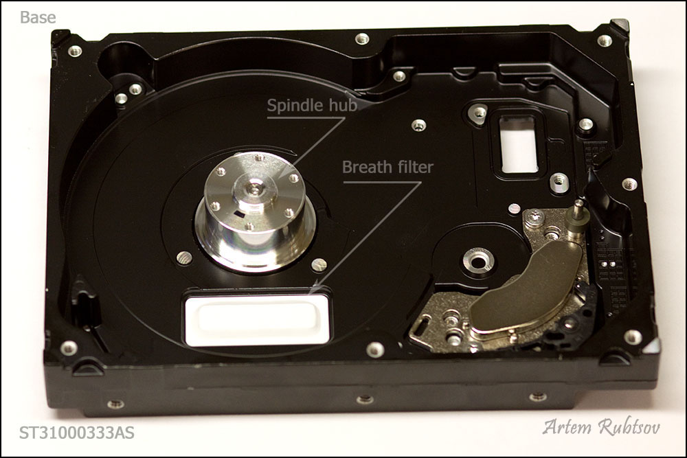
That's how the breath filter looks. And the breath hole is located right under the breath filter. Let's see the breath filter closer.
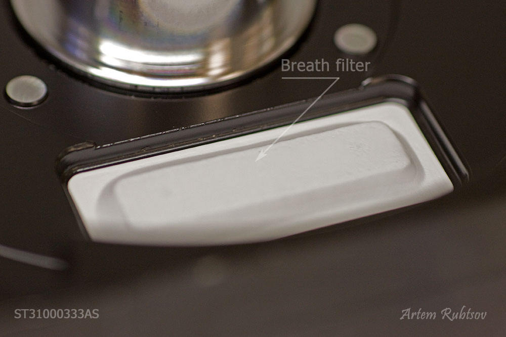
Because air from outside definitely has dust the breath filter has several layers of filtration and it's much thicker than recirculation filter, it also may have some silica gel inside to reduce air moisture.
This is it! Hard drive is completely disassembled.
This article has been written exclusively for hddscan.com
If you would like to publish or reproduce any part of this article on the other Internet recourses you would have to get an agreement signed by the author of this article.